Cartridge Mechanical Seal Installation Guide
Cartridge Seal
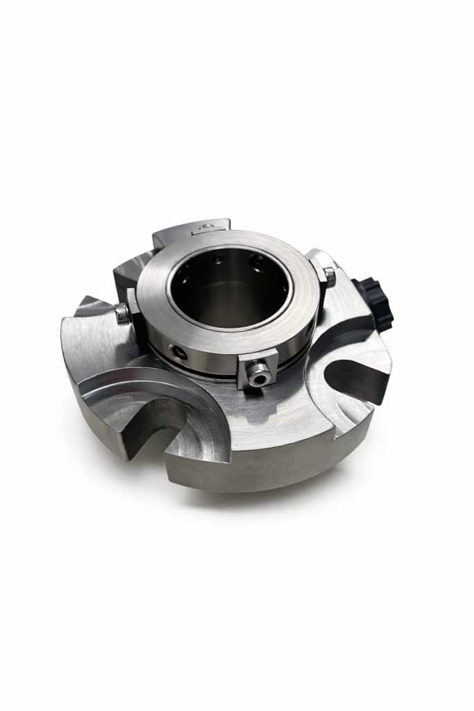
Our SMSC 1SV is a single cartridge seal built on an ANSI footprint. Style: Single cartridge, stationary design (suited for high-speed applications) Sizes: 1″ to 4″.
Learn how to install a cartridge mechanical seal correctly, prevent leaks, avoid overheating, and troubleshoot common cartridge seal startup problems.
A cartridge mechanical seal is installed by sliding the seal onto the shaft, tightening the gland bolts evenly, securing the set screws, and removing the setting clips before startup. Proper installation helps prevent leaks, overheating, vibration issues, and premature seal failure.
This guide is designed for anyone searching for how to install a cartridge mechanical seal, cartridge seal troubleshooting, pump seal installation steps, or why a cartridge seal leaks after installation.
Cartridge seals are designed to simplify installation compared to traditional component seals, but correct setup is still critical. Problems like uneven gland bolt tightening, excessive shaft runout, dry running, or failure to remove setting clips can cause immediate leakage or shorten seal life.
If you need a replacement after reviewing this guide, browse our cartridge mechanical seals and contact us if you need help matching the right seal for your pump.
Download the full step-by-step cartridge seal installation guide.
Get Free Cartridge Seal Installation GuideYes. Setting clips stay in place during installation, then must be removed before startup. Starting the pump with clips still installed can cause immediate leakage and seal damage.
Common causes include setting clips not removed, contaminated seal faces, uneven gland bolt tightening, excessive shaft runout, excessive axial end play, and worn bearings.
No. Dry running is one of the most common causes of overheating and premature mechanical seal failure. The pump should be properly flooded before startup.
- Lockout / tagout completed
- Pump depressurized and drained
- Shaft inspected for straightness and condition
- Bearings checked for wear and movement
- Shaft runout and axial end play verified
- Stuffing box face clean and free of burrs
- Seal faces protected from dirt, grease, and damage
- Gland gasket available and properly positioned
- Setting clips left installed until final mounting is complete
Before installing a new cartridge seal, confirm the shaft and seal chamber are within acceptable tolerances. Excessive movement is one of the most common reasons a cartridge seal leaks after installation.
- Bent shaft: Inspect the shaft with a dial indicator or between centers on a lathe. Replace the shaft if bent.
- Worn bearings: Bearing wear creates vibration and movement that can separate the seal faces and cause leakage during operation.
- Improper bearing fitment: If the shaft is not properly held in axial and radial directions, vibration and seal instability can occur.
- Damaged stuffing box face: Burrs, corrosion, or debris can prevent proper gasket sealing and cause gland leakage.
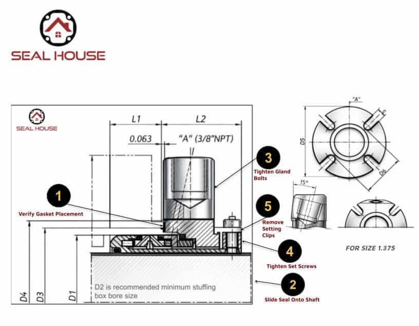
Visual reference for cartridge mechanical seal installation steps including gasket placement, shaft positioning, gland bolt tightening, set screw tightening, and setting clip removal.
This cartridge seal installation diagram shows the correct sequence to install a mechanical seal and avoid common failure issues such as leaks, overheating, and poor startup performance.
Follow these cartridge mechanical seal installation steps carefully. Matching the numbered diagram to the instructions below helps reduce installation mistakes and improves startup reliability.
Make sure the gland gasket is properly seated between the gland plate and stuffing box face. Incorrect gasket placement can cause immediate leakage around the gland.
Carefully slide the cartridge seal assembly over the shaft until the gland contacts the stuffing box face. Make sure the seal sits squarely and does not bind during installation.
Install and tighten the gland bolts or studs evenly using a cross pattern. Even compression helps maintain alignment and prevents gasket distortion.
Locate the cup-point set screws on the sleeve hub and tighten them securely to lock the seal sleeve to the shaft. Avoid overtightening that may damage components.
After the seal has been fully secured to the pump and shaft, remove the setting clips or locating tabs. Never start the pump with these clips still installed.
If the application requires flushing or quench service, connect the flush port labeled “A” (3/8" NPT) and verify flow before startup.
A proper startup procedure is just as important as the installation itself. Many cartridge seal leaks and overheating problems begin in the first few minutes of operation.
- Confirm all installation steps are complete
- Make sure all setting clips have been removed
- Rotate the shaft manually several turns
- Ensure the pump is flooded with product
- Start the pump with the discharge valve closed
- Slowly open the discharge valve to normal operating conditions
- Watch for leakage, vibration, noise, or heat buildup
After startup, inspect the pump and seal carefully for the following:
- Excessive vibration
- Seal overheating
- Abnormal noise
- Visible leakage
- Blocked or insufficient flush flow
If any of these conditions appear, stop the pump and inspect the installation before further operation.
Use this troubleshooting chart to identify common symptoms, possible causes, and recommended actions after installation or startup.
| Symptom | Possible Cause | Recommended Action |
|---|---|---|
| Seal leaks immediately at startup | Setting clips not removed | Stop pump and remove all setting clips |
| Seal leaks immediately at startup | Gland bolts not tightened evenly | Retighten gland bolts in a cross pattern |
| Seal leaks immediately at startup | Contaminated seal faces | Clean seal faces and reinstall |
| Seal leaks during operation | Excessive shaft runout | Verify runout does not exceed 0.003 in (0.08 mm) |
| Seal leaks during operation | Excessive shaft end play | Verify axial movement does not exceed 0.005 in (0.125 mm) |
| Seal leaks during operation | Worn bearings | Replace worn bearings |
| Seal runs hot | Dry running | Verify proper fluid supply before startup |
| Seal runs hot | Flush line blocked | Check flush port A (3/8" NPT) and verify flow |
| Excessive vibration | Bent shaft | Inspect shaft and replace if bent |
| Excessive vibration | Improper bearing fitment | Ensure shaft is locked in both axial and radial directions |
| Noise during operation | Pump cavitation | Check suction conditions and pump operating point |
Even with correct installation, a seal may need replacement if the equipment has worn components or the current seal has already been damaged. Signs you may need a new cartridge seal include:
- Seal leaking immediately after startup
- Excessive vibration or abnormal noise
- Seal overheating or evidence of dry running
- Visible wear on the sleeve, gland, or seal faces
- Repeated installation failures caused by equipment condition
If you are seeing any of these problems, browse our replacement mechanical seals or contact Seal House for help identifying the correct replacement for your pump and application.
If your current seal is leaking, running hot, or showing signs of vibration-related failure, Seal House can help you match the correct replacement.
One of the most common mistakes is starting the pump before removing the setting clips or clamps.
Immediate leakage can come from uneven gland bolt tightening, contaminated faces, or setting clips left in place. Leakage during operation may point to shaft runout, end play, worn bearings, or dry running.
Some applications do. This guide identifies a flush port labeled A with a 3/8" NPT connection for flush or quench lines when required.
Check shaft runout, axial end play, stuffing box condition, shaft straightness, bearing condition, and whether the stuffing box face is clean and free of burrs.
If the pump is started with setting clips installed, the seal cannot operate correctly and immediate leakage or seal damage can occur.
Gland bolts should be tightened evenly in a cross pattern so gasket compression stays uniform and the seal remains properly aligned.
Maximum shaft runout should not exceed 0.003 inches (0.08 mm) in the seal area.
Mechanical seal overheating is commonly caused by dry running, blocked flush lines, poor fluid supply, or improper startup procedure.
A cartridge seal is pre-assembled and easier to install consistently, while a component seal requires individual assembly and more precise manual setting during installation.
Yes. Worn bearings can create movement and vibration that separate the seal faces, increase leakage, and shorten seal life.
Still not sure which seal you need?
Seal House can help you identify the right replacement for your pump, dimensions, and application.
Contact Seal HouseCartridge Seal
Our SMSC 1SV is a single cartridge seal built on an ANSI footprint. Style: Single cartridge, stationary design (suited for high-speed applications) Sizes: 1″ to 4″.